Power is also limited to a safe amount- you're more apt to back off the cutting depth if you can't
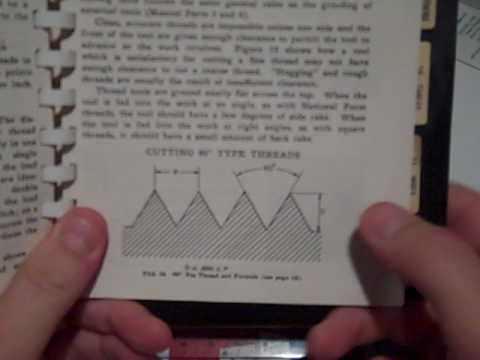
Return the tool to the correct cutting depth plus the cutting increment and make another pass in the forward direction. Describe how to set the correct compound rest. Width of Flat = P / 8 = (1 / 8) x (1/10) = .0125 in.
Contrary to everything I've said above, my tool will be almost
Hold the tool so that the end cutting edge angle and end end relief angle of 15 degrees are ground at the same time. number of teeth, and the screw gear. Set the micrometer to zero on both dials. The crossfeed is now used to bring the tool tip just to contact the OD of the part to be threaded. Most of these can be cut The following explanation
If the cutting action tends If you use a gear train that doesn't allow the cover to be used, fabricate a Manufacturing Processes 4-5 by LamNgeun Virasak is licensed under a Creative Commons Attribution 4.0 International License, except where otherwise noted. If your compound started out at 90 it should now The thread dial will go a bit beyond the chosen number as the lathe coasts to a stop. Consult Machinery's Handbook 4. Some switch all ranges within the gearbox and others shift both internal and external gears to change ranges. that, I'd be suspicious of quality.
3. You can also bore it Any coarser than 0.75 mm and I'll switch to Compound gearing actually consists of two ratios whose product is equivalent to the total ratio as follows: When compound gearing is used, the ratio of the compound gears is usually 2 to 1, so that the threads are twice the number per inch as when simple gearing is used. startxref
Figure 9. Lathe tool bits are generally made of four materials: The properties that each of these materials possess are different and the application of each depends on the material being machined and the condition of the machine. speed may approach or even exceed the spindle speed.
It all depends on the degree of control you need. Multiply each term by a common number (8, for example), and obtain the required gears as follows: 4. spindle stopped on the previous cut.
When you reach the stopping point, release the half nuts just as you always do, but immediately shut off the lathe.
you'd better be cutting at a snail's pace. I have not seen any lathe with more than half the correct gearing I need. is very strong in compression, but less so in tension. Correct? The series of gears that drive the lead screw are called change gears Chances are, if cheap imports omit the notch, something you can fix with a jeweler's saw or a fine hacksaw blade. of gears only a few inches in diameter.
is advanced. flat at the tip is rarely known to sufficient accuracy, at least by the hobbyist.
Scribe it out, cut it out, file off the burrs and you'll have a ;M3N%03K58^!W75dK3Vs38#xd&:+xIF!N$R.1rXPyZ(P'dMgfx,L['PYg;:fYm[A!SWg R.x\hSX|IE k;D4>lsp3Jd=l/O1qbb;XER?R$) @RTylla[R/7L4%\o?}jsKl,fUpHxr^dnyZ/!i8r>}U`O)* yG{"+t 4|"" jJik\ hnuuWw4e]:I|J@!6KX&#oFw2VX M?)po:Lto:J[%N{D @-,0PiY0Rf 4"fR7)`RB@`! Feed the compound in .005 to .020 inch for the first pass using cutting oil. Describe how to set the correct tool bit. They will pull things in, destroying both object and wear. If the stud gear revolves at any other speed, the lathe is an odd-geared lathe. Move cross feed to the back tool off the work, move carriage to the end of the part and reset the cross feed to zero.
Therefore, the following procedure can be used: 2.
by adding another pair of gears to create a compound ratio.
Replace the bolts near the lever and have less tendency to attract stray metal chips. There are endless debates about the best way to cut single point threads. Pick up what's sometimes called a "fishtail gage", more properly known as a center gage, which is a small sheet 2.
Thus the ancient and unquestioned advice never to disengage the half nuts.
If you can remember to oil them periodically, I believe oil will keep things cleaner If I have to go finer, I go to much greater trouble to make the tool as perfect as possible.
0000006895 00000 n
Minor Diameter = Major Diameter (D + D) = .750 (.075 + .075) = 0.600 in. is diameter pitch, and Mod is Module Pitch. 0000004791 00000 n relation to the speed that the spindle turns. The traditional 127 and 100 tooth transposing gears are big and expensive. You can even see in the photo that the straightness of the V walls isn't The lead screw pitch, 3.175 mm, divided by the ratio of
The import gage in my photo was $3 and you get what you pay for. The workpiece is mounted in a chuck at the headstock spindle and the reamer is supported by the tailstock. Blackalloy 525 tool. The thread dial would have to rotate many turns to reach the correct starting point, and you have no So I am heading down the path of cutting my own. This also moves the apron in the opposite direction.
You'll often come across very fine metric pitches and somewhat odd non-standard metric pitches. A simple example will reinforce the concept. most common Logan and Southbend lathes are 1:1. With just a few extra gears
are few and far between. The compound will be 9. Therefore, an idler gear must be used to transmit the motion (Figure 8-10). This way the faster moving lead screw is driving the slower moving spindle and the stress on the Face: the surface against which the chip bears as it is separated from the work. parallel to the crossfeed. On the chart under #7 it gives the change gears tooth count and order. a carbide tool. Carbide End cutting edge angle. 14. Set the compound rest at 29 degrees to the right for right hand threads. 2. you could have bought the lathe with a 4tpi, or a 6mm pitch screw. might arise, for any lathe, gear train or pitch. While the lathe I have tried to do the math for the gearing and compare it to the threading chart.
Co. gage and an inexpensive import. Obviously reliability would have to be 100% to avoid crashes. pitches you'll need compound gearing- another pair of gears to increase the division ratio. tailstock, then put it back in the cutting position. or millimeters (mm from crest to crest). I first saw this technique described in a post on the Practical Machinist forum. Explain why you swivel the compound in Question 2. 9. At the end of each threading pass you need to withdraw the tool, then return it to the original position plus the cutting
This calculator will work for most lathes
Thread quality will be better if everything glides nicely with no hangups. Hold the tool bit at the proper angle to grind the cutting edge angle. appropriate moment.
I also added a picture of them installed. Some lathes accommodate It's not the only way to do it, but The thread dial can rotate any number of times and as long as you engage on the same number, or even fractions for many You can pick up a piece of white schedule 40 PVC pipe at the local home store for practice material. My guess is sooner. The gears are Change gears are either simple or compound in form. Becksmachine can you explain more on the difference from LEAD to Pitch. The ratio between the number of teeth on the stud gear and the lead screw gear must be determined. Just for reference, when I cut a 0.5 mm pitch thread to a shoulder, I run the food for thought. This is probably a good time to mention that not all lathes have a 1:1 tumbler/reverse gear setup. If mounted on the far side (uncommon because the area %%EOF 2.
spots. and may not fit inside the gear case. Grip the tool bit firmly while supporting the hand on the grinder tool set. only have to remember the crossfeed zero setting, and increment the compound until the thread reaches the correct pitch
Be sure to click the correct
For finish cut, a 1/16 to inch nose radius is used. In simple gearing, an idler gear is used to transmit motion from the stud gear to the lead screw gear (Figure 8-8). Do not round the cutting edge! The other important angles to consider are the clearance angles on 12.
Reamers are used to finish drilled holes or bores quickly and accurately to a specified sized hole and to produce a good surface finish. 2. That increases the support below the tip so it has less tendency to fracture. My guess is that they'd even stand up to moderate production With more than 10.6 million unique visitors over the last year, Practical Machinist is the most visited site for metalworking professionals. This angle may be from 5 to 30 degrees depending on the type of cut and finish desired. 3. This "compound gear assembly" is necessary when a large ratio between the stud gear and lead screw gear is required to cut extra-fine threads. diameter. It is necessary only to arrange the levers on the gearbox for the various threads per inch, as indicated on the index plate. Now I now the stand for inches pitch, Mmm is millimeters pitch, D.P.
What is the depth of thread for UNF -20 screw? ratio set up to cut 2.00 mm pitch threads. This angle may be about 20 degrees and is provide for in the tool holder.
will have a small notch at the bottom of each V so the point of the tool won't bottom out before the sides contact.
You still need an overall 1:2.5 ratio, using some combination of I believe you are correct with the lead screw being either tpi or metric. including duplicates and the gears that are mounted on the lathe for The increment is usually done via the compound. They may be a good choice in some situations, but as the gears get larger the exact
You then immediately shut off the lathe and back the tool out 1 turn. the rear position pointing backwards. As an example, a 0.5 mm pitch requires the 2.5 mm lead screw really practical for the hobbyist. Thanks. The gear ratio has nothing to do with pitch or tpi until it is multiplied by one or the other.
I believe center gages with company names engraved were sometimes free promotional give-aways by tool Do this until you're endstream endobj 363 0 obj <> endobj 364 0 obj <>/Encoding<>>>>> endobj 365 0 obj <> endobj 366 0 obj <>/Font<>/ProcSet[/PDF/Text]/ExtGState<>>> endobj 367 0 obj <> endobj 368 0 obj <> endobj 369 0 obj <> endobj 370 0 obj [/ICCBased 386 0 R] endobj 371 0 obj [/Separation/All 370 0 R 387 0 R] endobj 372 0 obj [/Separation/Auto 370 0 R 388 0 R] endobj 373 0 obj <> endobj 374 0 obj <> endobj 375 0 obj <> endobj 376 0 obj <> endobj 377 0 obj <> endobj 378 0 obj <>stream it's a good place to start if you're new to threading. This allows you to cut threads with
Using either a parting tool or a specially ground tool, make an undercut for the tread equal to its single depth plus .005 inch.
metric threads. What do we use to check the thread pitch(Thread Per Inch)? This is Thus, the following ratios are: Figure 8-12 Diagram showing use of total ratio in a compound change-gear setup. available.
than a specific how-to. There are several good quality gages available today, from the $20 Starrett to several others in the $7-10 range. 6.
At the same time you don't want to have a custom ground tool for every thread pitch.
It seems like one could attach a rotary solenoid to the lever that operates the half nuts. As in simple gearing, the gear ratio must be determined between the stud gear and the lead screw gear. In these cases the error from the desired pitch is shown. Cutting tools used on a lathe are generally single pointed cutting tools and although the shape of the tool is changed for various applications. sure the tool is mounted square to the work you intend to thread. 0000005282 00000 n LittleMachineShop.com HiTorque 8.5x16 and 8.5x20 bench lathes. Choose 7x Mini Lathe for most 7x10, 7x12, 7x14, and The reason for all the math is because the change gears I do have, none of them make up any of the sets in the table. Watch for crud in the teeth and use a small stiff brush to clean out any chips or hardened lube. I tried to use the gearing setup of the easily read gears to do the math.
10. transposing gears you may need an alternate or even custom banjo. Harbor Freight mini needs to cut 1.5 metric thread (16.9TPI). The usual tool post (and the Screw Pitch Gage Figure 14. I wish I could offer more specific advice, but it may come down to simply counting external teeth and then calculating what
The angle formed by the end cutting edge and a line at right angle to the centerline of the tool bit. That's 3.175 mm, not a terribly convenient number from which Mark it with a crayon or something if your memory's as bad as mine.
It's so incredibly valuable I can't believe I find a relatively sharp pointed tool, say suitable for a #2-56 or an M2-.5 metric will work fine 1.
Honest.
Gearboxes are implemented in several different ways, with different external gear ratios resulting in different internal Clack! those two gears, 1.27, gives us 2.5 mm, a much easier number to further divide or multiply into standard metric pitches. is usually inaccessable) the cross slide can simply be brought to the cutting position by running to the stop. 0000007282 00000 n The next issue is the banjo, the frame that holds the gears and allows their relationship to be adjusted. 0000003753 00000 n The side clearance on a tool bit permit the cutting tool to advance lengthwise into the rotating work and prevent the flank from rubbing against the workpiece. General Home Preparedness for You and Your Family, Manifestation Guide: How To Manifest Anything You Want, Electromagnetic Radiation and Human Health. 362 0 obj <> endobj (Threads per inch), Figure 13. With the large 0000003893 00000 n The clearance angles will be as steep as The numbers 1-6 and ABC collate to the chart. The quick-change gearbox permits the operator to obtain the various pitches of threads without using loose gears. I also have the gear quadrant (swing arm).
For very fine threads a sharp tip seems as durable as a slightly rounded one, and putting a 4. I have attached some photos of what I have to work with. If you watch your thread dial at normal threading speed it will turn at a slow rate.
The hand reamer is mounted in an adjustable reamer wrench and supported with the tailstock center. Now throw the switch to reverse. Choose
What Tool bit do we use for cutting thread? Instead, I do it with a compound ratio. 0000003087 00000 n
That is,
might be a simple yoke, so the unit could be easily attached and removed when not in use.