This result is in agreement with the stability region depicted in Figure 11. Water flowing down a spillway can travel at very high speedsabout 160 km (100 miles) per hour in the case of a dam 100 metres (330 feet) highand form a standing wave where it enters the riverbed; it proceeds downstream at lower mean velocity but in a highly turbulent state. 2014, Article ID 874060, 13 pages, 2014. https://doi.org/10.1155/2014/874060, 1Department of Hydraulic, Energy and Environmental Engineering, Technical University of Madrid, 28040 Madrid, Spain. With arch dams it is convenient to construct gated openings in the shell structure at some distance below the crest of the dam, ensuring that the discharging jets fall well clear downstream. As stated in [9], it is worthy to mention that these expressions are independent of each other. A stability analysis based on the Routh-Hurwitz criterion is carried out and a practical criterion for tuning the gains of the PI controller is proposed. The automatic controlled lowering of Obermeyer Spillway Gates during flood events prevents upstream flooding and allows the impoundment to be periodically cleared of sediment which would otherwise pass through the hydropower plant shortening turbine life. Learn the fossil fuels definition. Hydroelectric Power Following the methodology described in [9, 13], the stability regions are determined and the PI gains adjusted.
This "safety valve" prevents water from spilling over the dam crest. In the considered plant configuration, friction losses are mainly due to the headrace conduit [9] and therefore friction losses in penstock can also be neglected. A restricted problem, in, M. Chaudhry, Governing stability of a hydroelectric power plant,, D. H. Thorne and E. F. Hill, Extensions of stability boundaries of a hydraulic turbine generating unit,, D. T. Phi, E. J. Bourque, D. H. Thorne, and E. F. Hill, Analysis and application of the stability limits of a hydro-generating unit,, S. Hagihara, H. Yokota, K. Goda, and K. Isobe, Stability of a hydraulic turbine generating unit controlled by PID governor,, T. Brezina, J. Kovar, and T. Hejc, Modeling and control of system with pump and pipeline by pole placement method, in, M. Mahmoud, K. Dutton, and M. Denman, Design and simulation of a nonlinear fuzzy controller for a hydropower plant,, K. Natarajan, Robust PID controller design for hydroturbines,, B. Strah, O. Kuljaca, and Z. Vukic, Speed and active power control of hydro turbine unit,, M. Han, B. Kawkabani, and J.-J. Learn about geothermal energy pros and cons and its different uses. If you continue browsing the site, you agree to the use of cookies on this website. Nowadays, the interest in run-of-river hydropower plants is increasing. The dynamics of each component is expressed by different equations as presented below. When the plant is working under flood conditions, the flow is calculated with the expression In order to study the influence of the surge tank and head pond dimensions in the stability of the power plant, the following parameters and are defined, as described in [9, 13]: Second, the spillway intake should be wide enough so that the largest floods can pass without increasing the water level in the reservoir enough to cause a nuisance to upstream property owners. Simond, Eigenvalues analysis applied to the stability study of a variable speed pump turbine unit, in, P. C. O. Silva, B. Kawkabani, S. Allign, C. Nicolet, J.-J. In practice, the first condition is always fulfilled, and the second condition may be shown to reduce to Hydropower projects and sustainable development, Generating station construction and refurbishment. We'll match it. Water level reference under normal conditions, Water level reference under flood conditions, M. R. Pelaez-Samaniego, G. Riveros-Godoy, S. Torres-Contreras, T. Garcia-Perez, and E. Albornoz-Vintimilla, Production and use of electrolytic hydrogen in Ecuador towards a low carbon economy,, L. Spitalny, D. Unger, and J. M. A. Myrzik, Potential of small hydro power plants for delivering control energy in Germany, in, J. L. Mrquez, M. G. Molina, and J. M. Pacas, Dynamic modeling, simulation and control design of an advanced micro-hydro power plant for distributed generation applications,, P. A. Frick, Automatic control of small hydroelectric plants,. ):Surge tank level with respect to tailwater level (m):Surge tank water level variation (p.u. Content generally available for advertising, promotional, merchandising, or other commercial uses. Tidal Energy Pros, Cons & Costs | How is Tidal Energy Used? The expressions (22) are applied for tuning PI gains of Ocaa II power plant both in normal () and in flood operating conditions.
High head hydropower plants also benefit from the utilization of Obermeyer spillway gates. In turn, Figure 13 shows the plant response under flood conditions, with spillway, in points A, B, and C. As it can be deduced from Figure 11, the plant response is stable with all pairs of gains (A, B, and C). For this purpose, a small perturbation stability analysis based on the Routh-Hurwitz criterion has been carried out. Chapter two-Classification of Hydroelectric Power Plants, Hydro power plant presentation project by pratik diyora 100420106008, Combined Cycle Gas Turbine Power Plant Part 1, HYDROELECTRIC POWERPLANTS : Major hydroelectric plants operational in India, Be A Great Product Leader (Amplify, Oct 2019), Trillion Dollar Coach Book (Bill Campbell). Our editors will review what youve submitted and determine whether to revise the article. The elements that define the hydraulic system are the head pond, the headrace tunnel, the surge tank, the penstock, and the turbine.  ), Reference height in the head pond with respect to tailwater level (m), Variation of the reference height in the head pond (p.u. This is an open access article distributed under the Creative Commons Attribution License, which permits unrestricted use, distribution, and reproduction in any medium, provided the original work is properly cited. Now customize the name of a clipboard to store your clips. ):Headrace conduit losses (p.u. Spillway modernization begins at Xcel Energy Cedar Falls Hydro, Man arrested in Lake Hallie, suspected of 5th OWI offense, Husband finds 70-year-old wife killed by family dog, Man facing 20 Eau Claire County charges in connection to sexual assault investigation, BA.5 COVID-19 Variant Dominant in E.C.
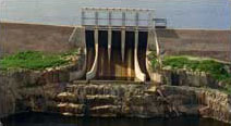
 Become a Study.com member to unlock this answer! The headrace conduit has been divided into six equal elements and the number of elements for the penstock is four. Figure 12 shows the plant response with the PI tuned with the gains corresponding to A, B, and C in the case without spillway, in normal conditions. (a) All coefficients of the characteristic polynomial (14) must be different from zero and of the same sign; (b) the elements of the first column of the Routh array must be positive. River flow, wicket gates position, water level in the head pond, and spillway flow, in normal operation (points A, B, and C). The notation used throughout the paper is defined in Appendix B. It is equal to zero in normal operation. Significant increases in annual generation may be achieved by the installation of Obermeyer spillway gates at low head hydropower plants. Run-of-river hydro plants allow harnessing the energy associated with water flows for other uses, such as water supply or irrigation, or the environmental minimum flows. Hydro Electric Power Plants, Hydraulic Turbines, Plant Selection, Hydro Graph, Learn faster and smarter from top experts, Download to take your learnings offline and on the go. From the stability analysis, it has been demonstrated that the existence of a spillway in the analysis improves the stability of the plant water level control; when the dynamics of the spillway is included (flood operation mode), the stability region covers a broader area than in normal operation mode (without spillage). ), reflected in the parameter (13), affect the stability of the plant, as can be seen in Figure 7. The instability observed for the pair of gains G confirms the results obtained from the linear model. Examine whether tidal energy is renewable or nonrenewable, and identify types of tidal energy sources. I can recommend a site that has helped me. ), Variation in headrace conduit flow (p.u. In the second case, the reference water level in the head pond is over the spillway (flood conditions). An obstruction known as a kicker, placed at the toe of the dam to project the water slightly upward, can move farther downstream the area in which erosion of the riverbed is most intense. Thus, for a practical implementation of this control scheme, a signal conditioner could be required. The upward lip is designed to project the jet of water dozens of metres into the air, which dissipates part of its energy and prevents structural damage. In [25, 26], the stability study and the tuning of the PID were carried out by eigenvalues analysis; oscillation modes were identified and associated with the different elements of the power plant.
 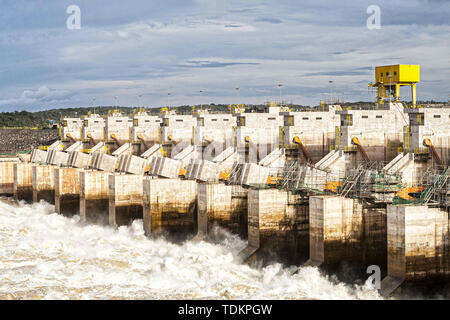 SlideShare uses cookies to improve functionality and performance, and to provide you with relevant advertising. Arch dams possess greater resistance to failure after overtopping. The main features of the plant are reflected in Table 1. We dont have enough spillway capacity here so if we got a big flood here we wouldnt be able to pass it and certainly if youve watched around the country youve seen episodes where dams have been over inundated by flood flow.. ), Base value of the wicket gates opening (mm), Reference height in the head pond (m.a.s.l.). With higher dams it is possible to deflect the jet of spilling water from a level above the base of the dam; this is known as a ski-jump spillway. Introducing , , and parameters, stability condition results in Finally, this criterion is applied to a real hydropower plant in design state; the importance of considering the spillway dimensions and turbine characteristic curves for adequate tuning of the controller gains is highlighted. First, the uncontrolled discharge of surplus water past the dam should be automatic and not dependent upon human control. Disaster is likely in the case of an earthfill, or embankment, dam that was not designed to permit uncontrolled flow of water on its downstream slope. All rights reserved. Enjoy access to millions of ebooks, audiobooks, magazines, and more from Scribd. The spillways at La Grande-3 and La Grande-4 have a curved design that looks like a ski jump. CEDAR FALLS, Wis. (WEAU) -A three-year project designed to strengthen the original structure at Xcel Energys Cedar Falls Hydro plant in Menomonie is underway. River flow, wicket gates position, water level in the head pond, and spillway flow, in flood operation (points A, B, and C). The water surface in the head pond in normal operation is below the spillway level. Then, the headrace tunnel dynamics is approximated by a rigid water column model (7). In the case of water level control in [8], it is found that with a PI controller a good response may be obtained; the derivative component could be affected by the noise transmitted with the sensor signal. Learn the definition of hydroelectric power and see examples. As it is shown in Figure 8, the stability region, when a part of the rivers flow is evacuated by the spillway, is bigger than the region obtained in normal operation. No related content is available yet for this article. Nishkam Dhiman Surge Tank. Get access to this video and our entire Q&A library. Obermeyer Spillway Gates allow spillway flows to be directed in the most beneficial manner. ):Integral gain of PI controller:Integral gain of PI controller (p.u. In [10] the use of a dead band for minimizing the regulator movements is analyzed. What is geothermal energy? Hydroelectric developments include flood-control structures designed to let excess water escape safely from the reservoir. Grand Coulee Dam in Washington state utilizes a spillway of this type. 1. Blockchain + AI + Crypto Economics Are We Creating a Code Tsunami? The SlideShare family just got bigger. The overall project consists of replacing the existing overflow spillway and small gates with six large Tainter gates and also a downstream stilling basin which will helps reduce the risk of eroding the riverbed at the dam. This phenomenal capacity corresponds to an exceptional flood likely to occur once every 10,000 years. In [24], the PID gains are analytically determined by pole placement; good performance was obtained in simulations and field tests conducted in a real plant. (iii)Size of run-of-river hydro plants is usually limited; therefore, these plants are connected to distribution networks and contribute to the development of distributed generation. If you continue browsing the site, you agree to the use of cookies on this website. Free access to premium services like Tuneln, Mubi and more. << /Type /XRef /Filter /FlateDecode /Length 118 /W [ 1 3 1 ] /Index [ 256 30 ] where the coefficients are However, the influence in the stability regions due to this change is quite small; so it will be neglected. Learn about the pros and cons of hydroelectric energy, or hydropower. Conclusions about the head pond and surge tank areas are drawn from the stability analysis. What is Geothermal Energy? River flow, wicket gates position, water level in the head pond, and spillway flow, in flood operation (points D, E, and F). Although the model used for both the stability analysis and obtaining the mathematical expressions of the controller gains is a linear model with certain simplifications, the model used for simulations is the nonlinear one described in Section 2 and includes penstock dynamics, as well as nonlinearities associated with losses in the conduits so as to obtain results closer to the real plant response. It is worth noting that the said expressions depend on the dimensions and flow evacuated by the spillway, the initial per unit headrace conduit flow, and the turbine parameters. This article was most recently revised and updated by, https://www.britannica.com/technology/spillway-engineering. A lumped parameters model has been used to represent the headrace conduit behavior [27, 29, 30]. The spillway has a discharge capacity of 16,280 cubic metres of water per second, about twice the flow of the Saint-Laurent at Montral. As can be seen in Figure 12, only in case B (, ) the plant response is stable. In Figure 5, the effect of varying the parameter is represented. See the disadvantages and advantages of fossil fuels. Minimum surge tank cross-sectional area according to Thoma criterion (m, Parameters of the linearized turbine equations, Gross head in the head pond with respect to tailwater level (m), Variation of the gross head in the head pond (p.u. To learn more about the $50M project, see here. As expected, the response for adjustment at point F results unstable. The plant layout can be seen in Figure 1. Read the winning articles. This value corresponds to head pond surface area in Ocaa II power plant: Ocaa II hydropower plant, located in Caar (Ecuador), is a run-of-river diversion plant just downstream Ocaa I power plant which is operating nowadays in Caar River. On the other hand, it has been found that the fulfillment of the well-known Thoma stability condition is not necessary in this case. The results of the previous stability analysis, as well as the followed PI tuning criterion, have been applied to a hydropower plant that is currently in design stage. For example, in [34] some strategies for obtaining an appropriate response were proposed but in the context of load-frequency control. The adjustment of the PID gains has been studied by several authors aiming to obtain a good dynamic response; among the first contributions, it is noteworthy to mention the works by Hovey and Paynter [15, 16]; in [17], the Routh-Hurwitz criterion is applied to define the stability region. There is an increasing need to develop clean energy technologies to cope with the problems relating to climate change, sustainable development, and energy security. /Root 258 0 R Different algorithms for controlling the water levels in three or more cascade hydro plants are presented in [7, 12]. The controlled pond level provided by the Obermeyer Spillway Gate System allows formation of stable ice cover, thus reducing the formation of fragile ice that otherwise obstructs the intake trash screen. The characteristic polynomial (13) of the linearized system has, in general, four conjugate complex roots: :Wave celerity in the conduit (m/s):Head pond cross-sectional area (m2):Surge tank cross-sectional area (m2):Headrace conduit cross-sectional area (m2):Minimum surge tank cross-sectional area according to Thoma criterion (m2):Penstock cross-sectional area (m2):Parameters of the linearized turbine equations:Spillway coefficient:Gravity acceleration (m/s2):Net head (m):Base head (m):Gross head in the head pond with respect to tailwater level (m):Variation of the gross head in the head pond (p.u. Other authors have worked using the pole placement for tuning the governor gains. In the three figures, the area under the curves determines the stable region, that is, the combination of and that guarantees a stable operation of the level control system. is equivalent to a spillway with a length of 7.5m in a head pond of 900m2 and considering 0.5m for the height of water level above the spillway. where is the proportional gain and is the integral gain. ):Proportional gain of PI controller:Proportional gain of PI controller (p.u. Stability regions: comparison of normal and flood operation. Although in more recent works advanced control techniques have been applied [22], the interest for robust PID controllers is still active [23]. copyright 2003-2022 Study.com. The isolated operation of small hydro plants in remote areas is considered in [5]; the power-frequency regulation would be provided by changing the turbine speed, when the discharged flow through the turbine is lower than the available river flow; thus, variable-speed generation equipment is required. SlideShare uses cookies to improve functionality and performance, and to provide you with relevant advertising. River flow, wicket gates position, water level in the head pond, and spillway flow, points G and H in flood operation.
The root-locus technique has also been applied to the adjustment of PID gains [20, 21]. County. We are preparing your download. (1)The real part of each pair of conjugated poles should have approximately the same value so that the settling times are similar and the appearance of a slow pole is avoided. A PI regulator modifies the wicket gate opening in order to maintain a constant water level in the head pond. In addition, analytical expressions, based on a heuristic criterion, have been obtained for both the proportional and integral gains in flood operation conditions. Compare advantages and disadvantages of geothermal energy. In this paper, the stability of a run-of-river diversion hydropower plant with a spillway in the head pond that evacuates a portion of the river flow is analyzed. /ID [<31442D30322D43462D35332D42372D30>] See our User Agreement and Privacy Policy. The following linearized expressions are obtained. In flooding operating conditions, the excess flow is discharged through a spillway; in this case, the water level reference is changed in order to allow controlling the spilled flow as in [14].